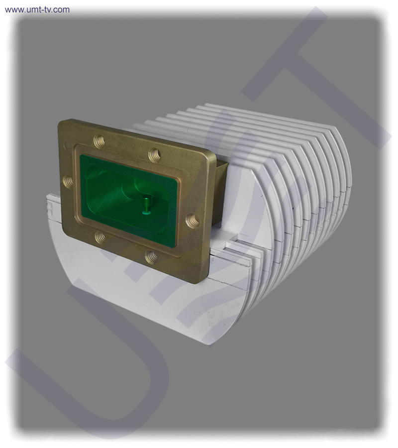
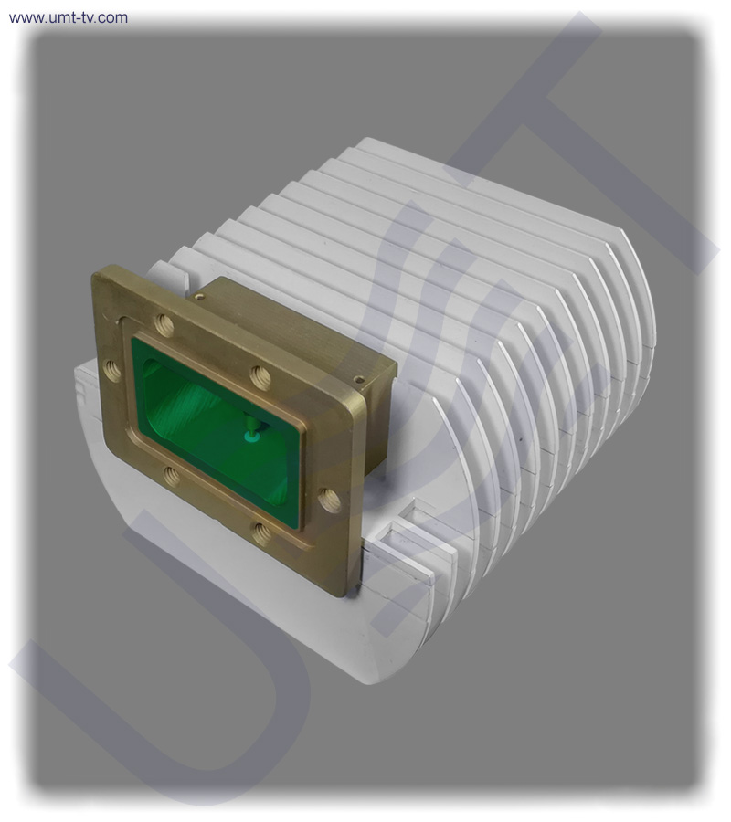
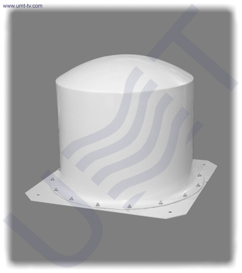
4W C-band block up-converter BUC-C04 is designed for MVDS TV broadcasting systems application in accordance with DVB-S/S2, DVB-C or DVB-T standards (fill the form of needed parameters using “customized equipment” button) and operates with up to 25 carriers. BUC-C04 has integrated matched coaxial to waveguide transition and can be used with regular radio-relay link (directional) or broadcast (sector and OMNI) antennas. BUC-C04 supports the following modulation types: 16APSK, 256QAM and COFDM (you may choose the modulation type while filling the “customized equipment” form). The local oscillator of BUC-C04 is locked by PLL with internal frequency reference and has the best linearity parameters to ensure the stability of the output frequency and low IMD3 level (these parameters are very important for high quality modulation). BUC-C04 provides 4 – 4.2 GHz output frequency range (or any 200 MHz in C-band) for 470 – 670 MHz input frequency range (either any other UHF or L-band – by order).
KEY FEATURES:
- Integrated matched coaxial waveguide transition
- Output power (P1dB, min): 4W
- Output frequency range: 4 – 4.2 GHz (or any 200 MHz in C-band by order – fill the “customized equipment” form)
- Input frequency range: 470 – 670 MHz (you may choose other UHF or L-band – fill the “customized equipment” form)
- Gain (min): 60 dB
- Highly stable internal frequency reference
- LO is locked by PLL with internal frequency reference
- IMD3 level at ALC output power (the lowest value): -45 dBc max
- Operates with up to 25 carriers
- Supports: 16APSK, 256QAM and COFDM
| Input parameters |
| Input frequency range |
470 – 670 MHz (UHF or L-band (by order) – fill the “customized equipment” form) |
| Input impedance |
50 Ohm |
| Input level, max |
-10 dBm |
| Input VSWR, max |
1.5 |
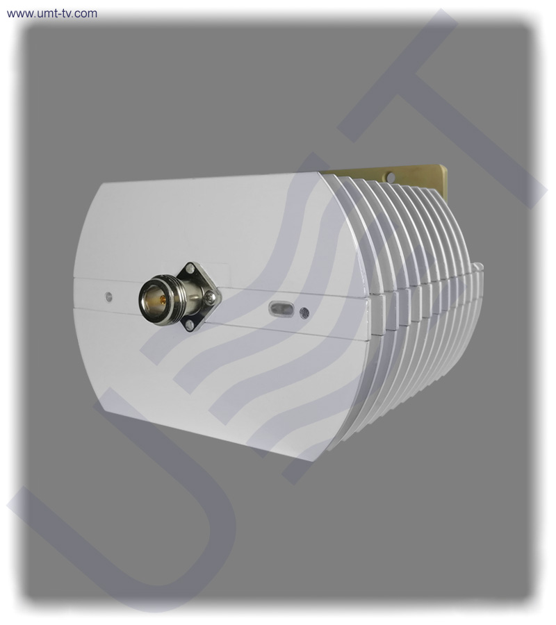
| Input interface |
N-type Female |
| ALC rage, min |
25 dB |
| ALC threshold level |
-35 dBm |
| Local Oscilator |
| LO frequency |
4670 MHz (or by order) |
| LO phase noise: |
| @1 kHz |
-80 dBc/Hz |
| @10 kHz |
-90dBc/Hz |
| @100 kHz |
-100dBc/Hz |
| LO instability |
± 2ppm |
| Output parameters |
| Output frequency range |
4000 – 4200 MHz (or any 200 MHz in C-band by order) |
| Output Power @P1dB |
4 W |
| ALC Output Power |
400 mW |
| Gain, min |
60 dB |
| IMD3 level at ALC Output Power, max |
-45 dBc |
| Output interface |
Waveguide WR229, Flange PDR40 |
| Output VSWR, max |
1.3 |
| Frequency Response |
| Flatness over Full Band |
±1 dB |
| Spurious |
| In-band @P1dB, max |
-50 dBc |
| Out-Band, max |
-60 dBc |
| LO leakage at ALC output power, max |
40 dBm |
| Image rejection, min |
60 dB |
| Power Supply |
| Input voltage |
18 VDC – 30 VDC, nominal 24 VDC |
| Power consumption, max |
17 W |
| Environmental |
| Operating temperature |
-40℃ to +50℃ (-40℉ to +122℉) |
| Storage temperature |
-60℃ to +80℃ (-76℉ to +176℉) |
| Operating humidity |
100%, non‐condensing |
| Mechanical |
| Dimensions (W x H x D) |
130x80x175 mm |
| Weight |
1.8 kg |