


TV LINK
TV Link communication scheme:

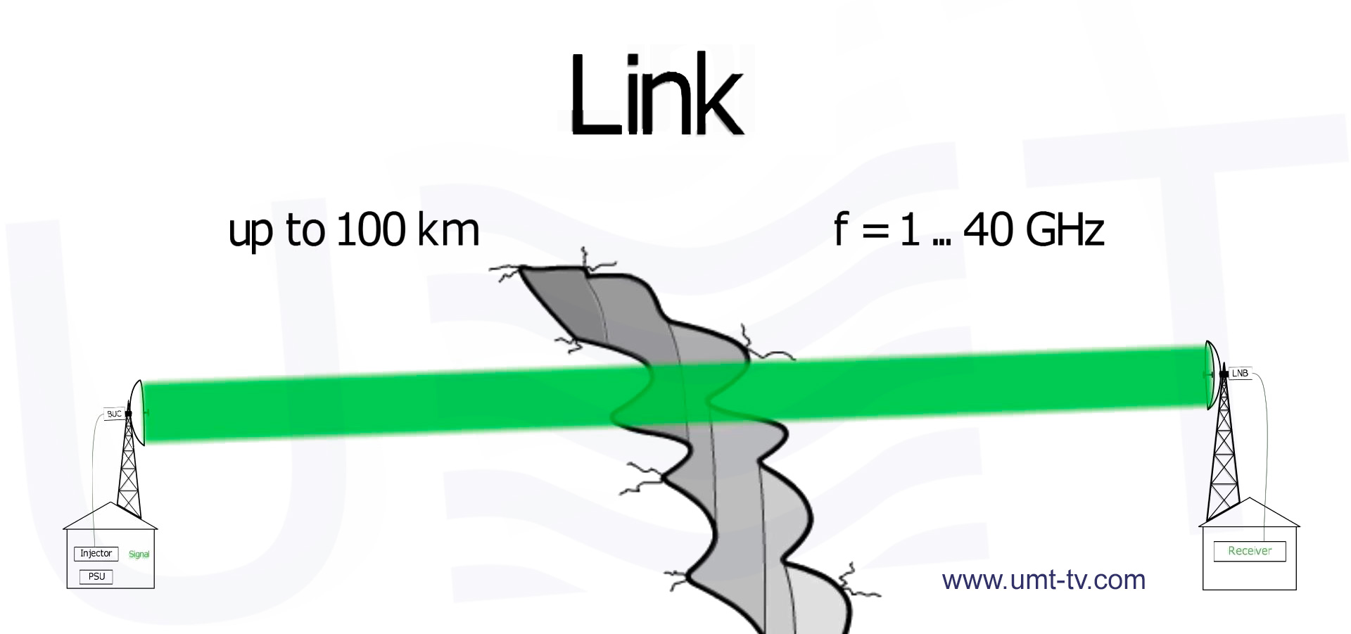
On the diagram shown previously you may see the main principle of TV link building.
Professional TV link includes two main parts: transmitting (Tx) and receiving (Rx) (on the diagram Point A and Point B respectively between which could be the distance of up too 100km).
Tx commonly consist of:
- PSU (power supply unit) – needed to supply power to Power injector.
- Power injector – required for both passing the RF-signal and supply voltage to BUC or LNB.
- Input RF-signal – L-band stream produced by a modulator.
- BUC (block up converter) – required for transforming L-band signal into Ku/K/Ka/etc. band. Our BUC also has AGC function – it is very important for stable broadcasting.
(About combining a number of different RF-carriers/signal into one spectrum you may read in the following article Wireless TV Broadcasting where you can find respective diagram). - Antennas for Tx and Rx are commonly used a directed and a sector types with respective radiation pattern, gain, polarization, etc. (see parameters in the respective tab on the page of antenna).
- LNB (low noise block) – it is like BUC but frequency conversion occurs vice versa: from Ku/K/Ka/etc. band into L-band.
- Output RF-signal on the Point B side is the same signal which was transmitted from Point A.
The required BUC power for covering exact distance, reachable distance depending on exact BUC power, calculate directed parabolic antenna gain at receiving and transmitting sides can be calculated using our own link budget calculator.
Of course other are a lot of other additional cable, waveguide and other associated equipment needed for TV link stations. We have all the list of needed equipment and we’re ready to help you to make a right choice and discuss all unintelligible moments.
Our links are designed mainly for TV broadcasting. Modulation standards used: DVB-S/S2/C/T/T2. Thus, no any converters needed for TV signal distribution – the signal from the Head-End can be directly submitted to the link transmitter. Links are developed in several bands with frequency plans lying in the frequency range from 1 to 40 GHz. They are mainly designed to transmit a television programs multiplex or E1/E3 plesiochronous hierarchy signals. Our links have wide frequency range and can conquer distances up to 100 km per one hop. Number of hops is not limited and depends on your line length. Links has approved their reliability by years of permanent work in hard environmental conditions. Properly designed link is even more robust than fiber because fiber can be damaged or torn by accident or disaster. Combined with our repeater, the link allows to expand the coverage zone far beyond the LoS of the TV broadcasting station. It is especially actual in highland area.
Characteristics:
| Parameters | Value |
|---|---|
| Link length, km | up to 100 per one hop |
| Frequency range, GHz | from 1 to 40 |
| Standards | DVB-S/S2/C/T/T2 |
| Number of carriers | from 1 to 25 |
| Operating modes | simplex and duplex |
| Antenna type | short-focus (minimal side radiation) |
| Built scheme | individual |
| Monitoring and management | remote (optional) |
Detailed description of main principle to build of TV link is shown here: