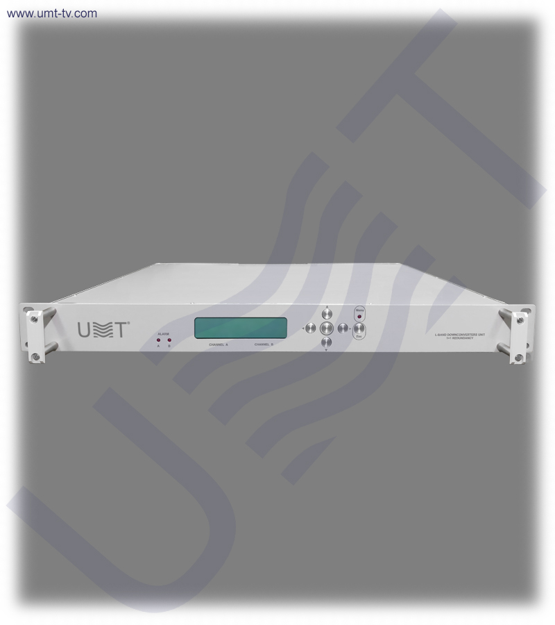
Downconverter with 1+1 redundancy from L-band to 70 MHz IF is a basic chassis on which are located: frequency converter module, controller board and indicator.
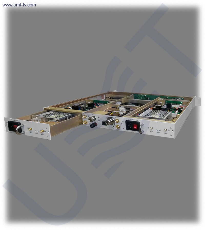
Automatic hot redundancy of the downconverter and power supplies are provided according to the 1+1 redundancy scheme. Therefore the design of the downconverter provides automatic switching to the spare (redundant) block in case of failure of one of the blocks and allows quick replacement of the failed block without interrupting the service of the spare block which is included in the delivery kit.
For adjusting the gain of downconverter it is applied the variable 30dB step attenuator in the radio frequency path.
Downconverter 1+1 is a professional L-band to 70 MHz IF frequency downconverter engineered for high-availability satellite communication, digital TV systems and mission-critical RF infrastructures. Built with dual hot-swappable converter blocks, it ensures uninterrupted operation even in the event of hardware failure. With dual-conversion (L → 2400 MHz → 70 MHz), low phase noise and a 30 dB step attenuator, it provides exceptional signal purity required for DVB-S/S2, telemetry, VSAT, MVDS and broadcast applications.
Designed for 24/7 service, the Downconverter 1+1 integrates advanced PLL monitoring, redundant AC/DC power supplies, RF/IF fault detection and automatic switchover logic. Operators gain precise control of gain, IF output levels and RF filtering directly from the front-panel interface or remotely via Ethernet. The 1U rackmount chassis makes it ideal for ground stations, teleports, broadcast headends and satellite uplink/downlink installations.
✅ Redundant L-band to 70 MHz conversion with hot-swap architecture
This downconverter utilizes a true 1+1 redundancy system with hot-swappable converter blocks, ensuring continuous IF output under all operating conditions. Automatic fault detection monitors the RF level, IF level and PLL lock status across both conversion stages to instantly select the active module. Engineers can replace a failed converter block without shutting down the system, preserving IF continuity in broadcast and satellite networks.
✅ High-accuracy dual-conversion downconversion chain
Using dual-conversion (L-band → 2400 MHz → 70 MHz), the system minimizes phase noise, spurious responses and distortion in the IF output. With frequency steps as fine as 1 kHz and frequency stability of 0.01 ppm, the downconverter maintains exceptional accuracy and long-term reliability. Its multi-stage RF filtering ensures clean signal extraction even in dense satellite carrier environments.
✅ Comprehensive local and remote management for RF infrastructure
Front-panel buttons, an LCD interface and Ethernet 10/100 allow complete monitoring and control of gain, attenuation, switching logic and converter health. Remote telemetry enables operators to track PLL alarms, RF/IF fault statuses and module state for integration into NMS systems. The step attenuator provides up to 30 dB of adjustment, ensuring consistent IF output levels across variable RF conditions.
🛠️ The Downconverter 1+1 provides operators with a robust, fault-tolerant solution for critical RF conversion paths. Its automatic switchover logic instantly activates the backup module when RF, IF or PLL abnormalities occur, preventing service interruptions. Hot-swap capability ensures field technicians can replace a failed module without powering down the system or disrupting the on-air signal.
🛒 The Downconverter 1+1 is ideal for professional satellite, RF distribution and digital broadcasting facilities that demand maximum uptime. With remote Ethernet control, alarm reporting and precision frequency stability of 0.01 ppm, it fits seamlessly into modern monitoring and redundancy architectures. Operators benefit from stable 70 MHz outputs, exceptionally low spurious levels and broad input tuning from 950–2150 MHz.
📌 Key features
-
Advanced 1+1 redundant downconversion system
This downconverter includes two fully independent converter modules that operate in hot-standby mode. When one unit fails or produces an alarm, the backup module immediately takes over without interruption. This ensures continuous 70 MHz IF delivery in mission-critical satellite, broadcast and teleport environments.
-
Dual-conversion architecture (L-band → 2400 MHz → 70 MHz)
The double-conversion design significantly improves spectral purity and reduces spurious emissions. It allows the device to maintain low phase noise and stable IF characteristics even in congested RF environments. This architecture is ideal for DVB-S/S2 reception, VSAT gateways and professional RF measurement systems.
-
30 dB step attenuator for precise gain control
A built-in 30 dB variable attenuator allows operators to fine-tune output levels with 1 dB resolution. This ensures consistent IF power for modulators, demodulators, analyzers and monitoring receivers. It also compensates for fluctuations in L-band input levels and cable losses.
-
Full PLL alarm monitoring and LED indicators
Integrated PLL supervision monitors both frequency-conversion stages for lock stability. Any unlock condition triggers the ALARM system and LED indication, enabling immediate troubleshooting. This makes it highly dependable for environments requiring continuous integrity verification.
-
Hot-swappable converter and PSU modules
Both the converter modules and AC/DC power supplies can be replaced without powering down the chassis. This dramatically reduces downtime and simplifies maintenance during live operations. The system is optimized for 24/7 field deployment.
-
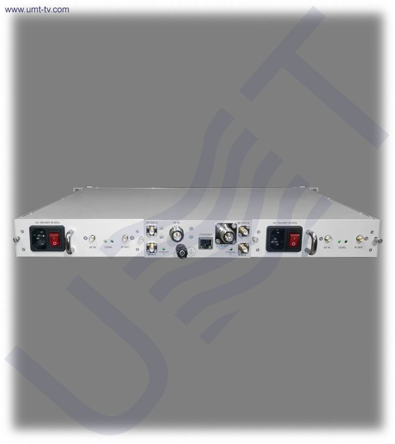
Front-panel and Ethernet remote control
Operators can configure all parameters locally using LCD and keypad, or remotely through Ethernet 10/100 Base-T. Remote access supports integration into centralized NMS systems for automated management and diagnostics.
⚙️ Main functions
-
Automatic redundancy switching (1+1 mode)
The unit continuously compares RF levels, IF levels and PLL status of both modules. When a failure is detected, it automatically activates the backup module within milliseconds. This provides uninterrupted 70 MHz output without operator intervention.
-
L-band to 70 MHz downconversion for satellite and TV systems
Converts wide L-band frequencies (950–2150 MHz) to standardized 70 MHz IF for demodulation and processing. It supports DVB-S/S2, telemetry, radio links and advanced monitoring systems using IF architectures.
-
Local and remote gain adjustment
The 30 dB step attenuator allows precise gain configuration to match system requirements. Operators can adjust gain via the front panel or remotely, ensuring accurate output levels across various RF environments.
-
Integrated alarm detection and reporting
The system analyzes four parameters — RF input, IF output, and PLL lock of both conversion stages. Alarm data is processed by the detector module and passed to the backup switching logic. This enables automated failover in redundant installations.
🧩 Applications
-
Satellite ground stations, VSAT hubs and teleports
The downconverter ensures stable 70 MHz IF for demodulators, spectrum analyzers and monitoring receivers. Its redundancy system guarantees uninterrupted operation even in harsh RF conditions. This makes it ideal for primary satellite distribution and monitoring infrastructure.
-
Broadcast and MVDS headends
Regional and national broadcast centers rely on clean IF signals for re-modulation, frequency conversion and distribution. The 1+1 redundancy ensures that live television services remain active even if one converter fails. Its low-phase-noise output enhances overall network stability.
-
Redundant converter racks in mission-critical RF systems
Perfect for installations requiring N+1 or 1+1 redundancy with automatic switching logic. Integrates easily into uplink/downlink chains, military communication nodes and aviation telemetry systems. Ensures fault-tolerant RF signal paths under continuous load.
-
Laboratories and RF test environments
The precise tuning (1 kHz step) and ultra-low phase noise make it ideal for controlled measurements. Engineers can evaluate satellite carriers, generate reference IF signals and test modulators/demodulators with high accuracy.
💡 Why you should buy from us❓
- 1.5 years warranty
- 7 years after-sales support
- Remote support team of engineers
- Discount program for regular customers 🎁
💬 Contact Us
For additional details or assistance regarding the Downconverter 1+1, feel free to contact our team. We provide professional consultation and aftersales support to help with installation and setup, ensuring you get the most out of your broadcasting equipment.