MVDS BROADCASTING
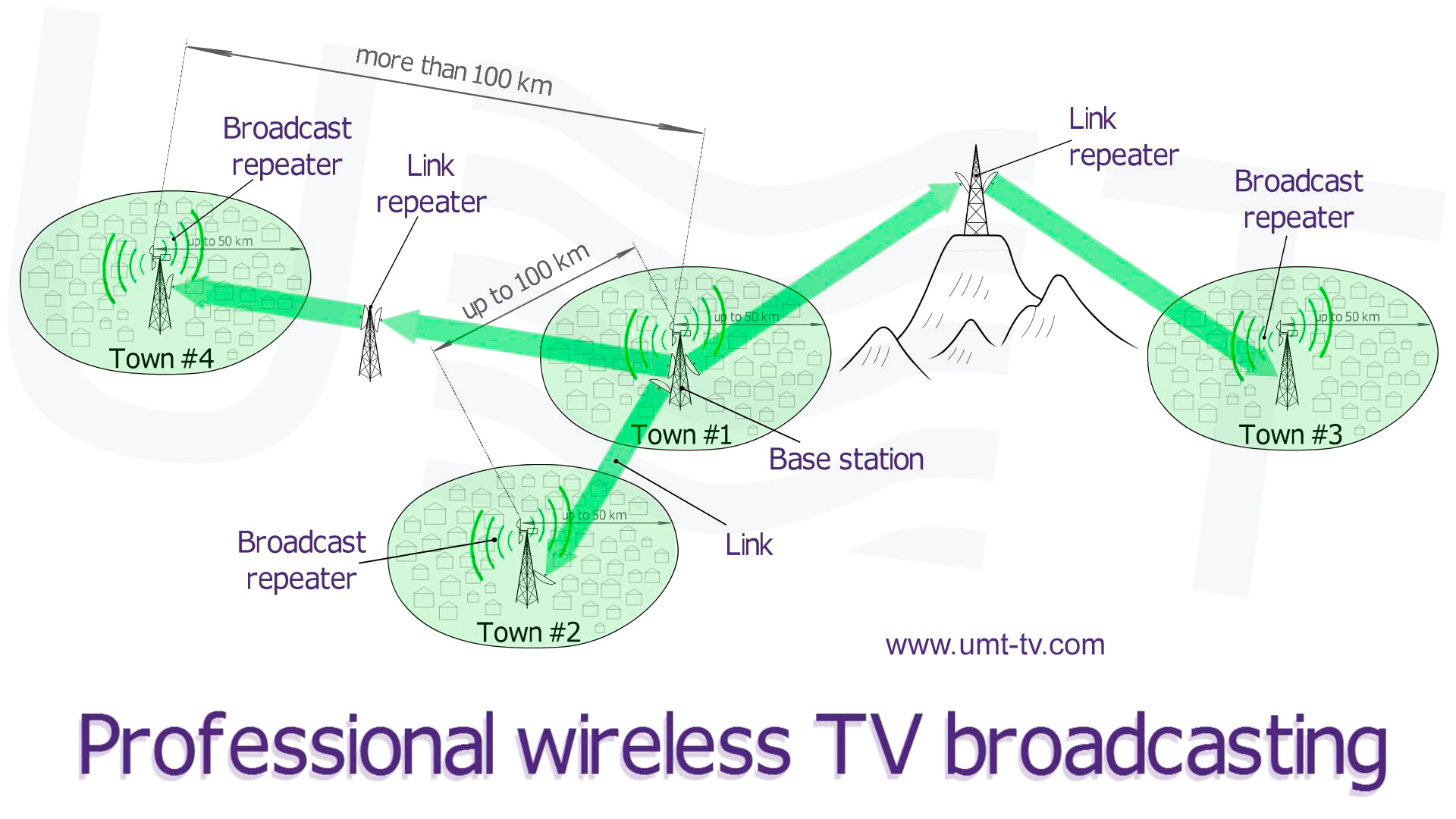
Most of the territory of many countries has a single-storey buildings and a low population density. In addition, there may be areas with complex terrain (e.g. mountains) inside the country, where the wiring is economically disadvantageous or even impossible. The installation of powerful TV transmitting centers with large coverage zones in such regions is impractical. An alternative to high-power broadcasting systems are low-power systems with relatively small coverage zone, but on the other hand, have a low cost and require low capital investments for their deployment. The first task of these systems is to provide high-quality multi-program television for residents of small towns. The television programming sources for broadcasters with such systems can be large television centers, RRLs, satellite teleports, the local studio, etc.
| Parameter | MVDS (MITRIS)(Ku-band) |
|---|---|
| Operation frequency range, GHz | 10.0 - 13.5 (basic, any other is possible by request) |
| Broadcasting standards | DVB-S/S2/C |
| Modulation types | QPSK, COFDM, 8PSK, 16APSK, 32APSK, QAM, QAM16, QAM64 or QAM256 |
| Coverage zone with one transmitter | up to 50 km |
| Repeater Hops without regeneration | up to 3 |
| Repeater Hops with reregeration | unlimited |
| A possible way to receive | individual and collective |
The UMT company develops, manufactures and installs the microwave TV broadcasting systems intended for operation in LoS mode. In all our MVDS (10.0 – 13.5 GHz) systems we use original technical solutions based on the technologies, which are protected by Patents № 24643, № 54275 and № 54644. UMT systems feature high power-efficiency, eco-friendliness and can be completed up to 90% by our own manufacture products. Our broadcasting systems are installed and operate in many countries with different climatic zones.

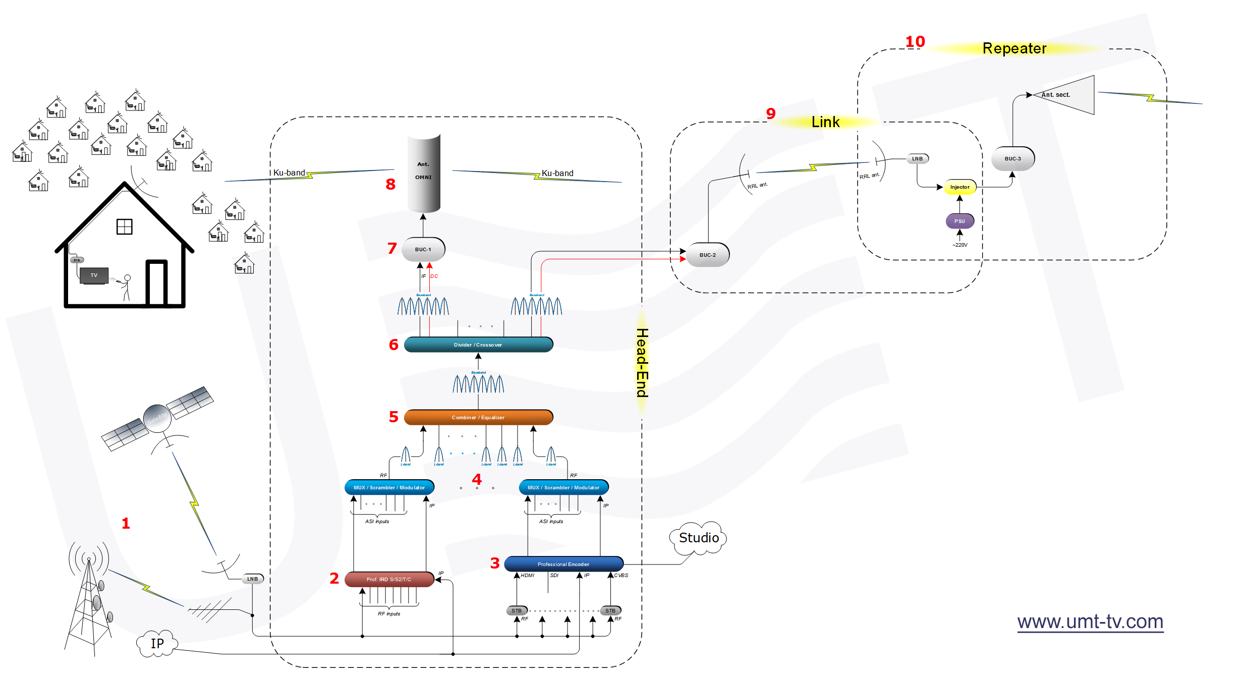
On the diagram shown below you may see the main principle of MVDS / MITRIS system building. It includes three main parts: head-end, link and repeater. Head-end in turn consists of:
- The source of the signal (main content for encoding, streaming, broadcasting, etc.)
- IRD. It is professional DVB-S/S2/T/T2/C/IP receiver – integrated receiver and descrambler/decoder.
- Encoder. Professional studio device for receiving CVBS, SDI, HDMI, IP, etc. signals and encoding them into ASI/IP transport streams.
- Scrambler. Our DVB/S/S2/C scramblers, except scrambling module, include also multiplexer, DVB/S/S2/C modulator and IP streamer (by UDP/RTP protocols). It is independent server which works with signal and contain subscribers database inside.
- Combiner. This device combines each carrier from scrambler into one spectrum. And our combiners have equalizing option which helps to make the spectrum strong and linear on the way of some cable and other attenuations.
- Crossover. This device divides the input RF-spectrum into few independent but equal to each other RF-spectrums. It helps to pass the RF-spectrum into different broadcasting parts: to subscribers side, to TV link (to transmit the signal for a long distance from main station to the other broadcasting center).
- BUC. This is block up-converter used for converting L-band spectrum into Ku/K/Ka/etc. band. Our BUC also has AGC function – it is very important for stable broadcasting.
- Antenna. We have omni-directional (for 360° broadcasting), sector (for broadcasting and repeater stations) and directed (for broadcasting and link stations) antennas.
- TV link. Station used for transmitting signal into long distances in difficult terrain conditions, where the cable connections are very complicated or even impossible.
- TV repeater. Station used for retransmitting and amplifying signal. It is useful in the regions not only where the cable and other connections are impossible but also when needed to transmit signal into so long distances when other type of transmitting variants very complicated and expensive.
The required BUC power for covering exact distance, reachable distance depending on exact BUC power, calculate directed parabolic antenna gain at receiving and transmitting sides can be calculated using our own link budget calculator.
The brutto and netto bit rates, satellite and occupied bandwidth and, which is most important, the possibility to analyze, basing on calculated bit rate, the number of HD and SD channels which can be included into the stream for different DVB standards (DVB-C, DVB-S, DVB-S2, DVB-S2X) can be calculated using our own bit rate calculator.
Of course other are a lot of other additional cable, waveguide and other associated equipment needed for each head-end, TV link and TV repeater stations. We have all the list of needed equipment and we’re ready to help you to make a right choice and discuss all unintelligible moments.
Main principle to build of MVDS / MITRIS:

Detailed description of main principle to build of MVDS / MITRIS is shown here: