
2226
Downconverter
Short description
Downconverter is designed to convert signals from L-band to 70 MHz IF for further signal processing on this IF. It is used in satellite communication systems of L, S, C, X and Ku bands.
Request for customized equipment HEAD-END
-
Description

-
Downloads

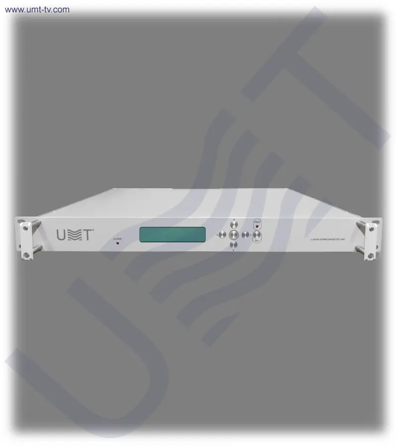
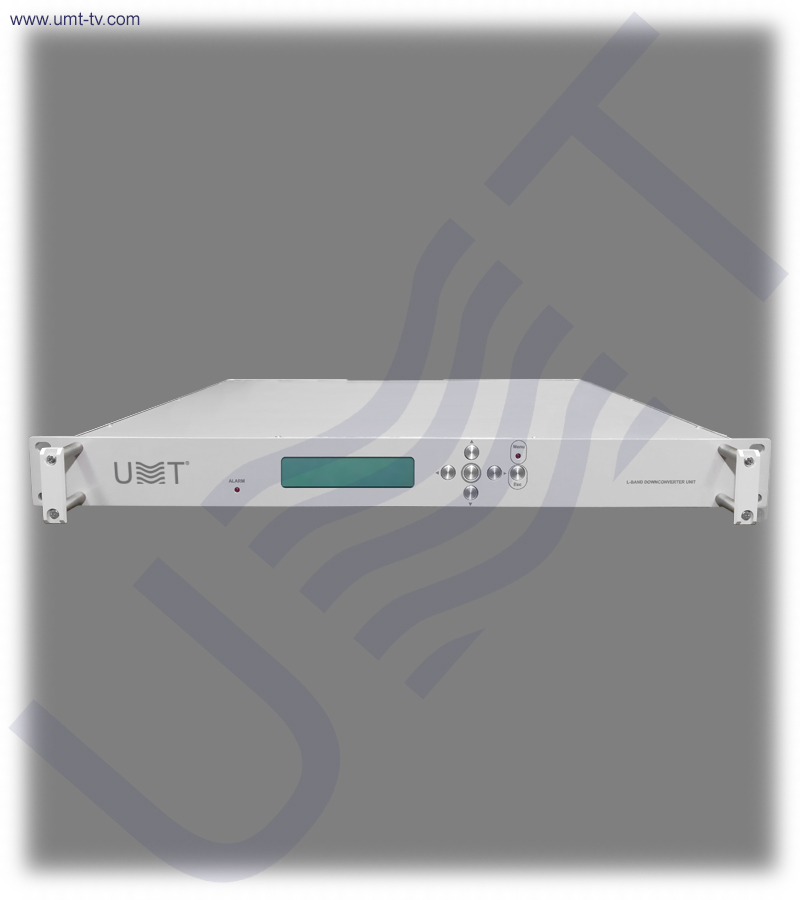
Downconverter from L-band to 70 MHz IF is a basic chassis on which are located: frequency converter module, controller board and indicator.
There is applied variable 30dB step attenuator in the radio frequency path for adjusting the gain of the downconverter.
KEY FEATURES:
- The frequency converter module is downconverter with a double frequency conversion (L / 2400 MHz / 70 MHz).
- The signal in the receiver part passes through three stages of filtration.
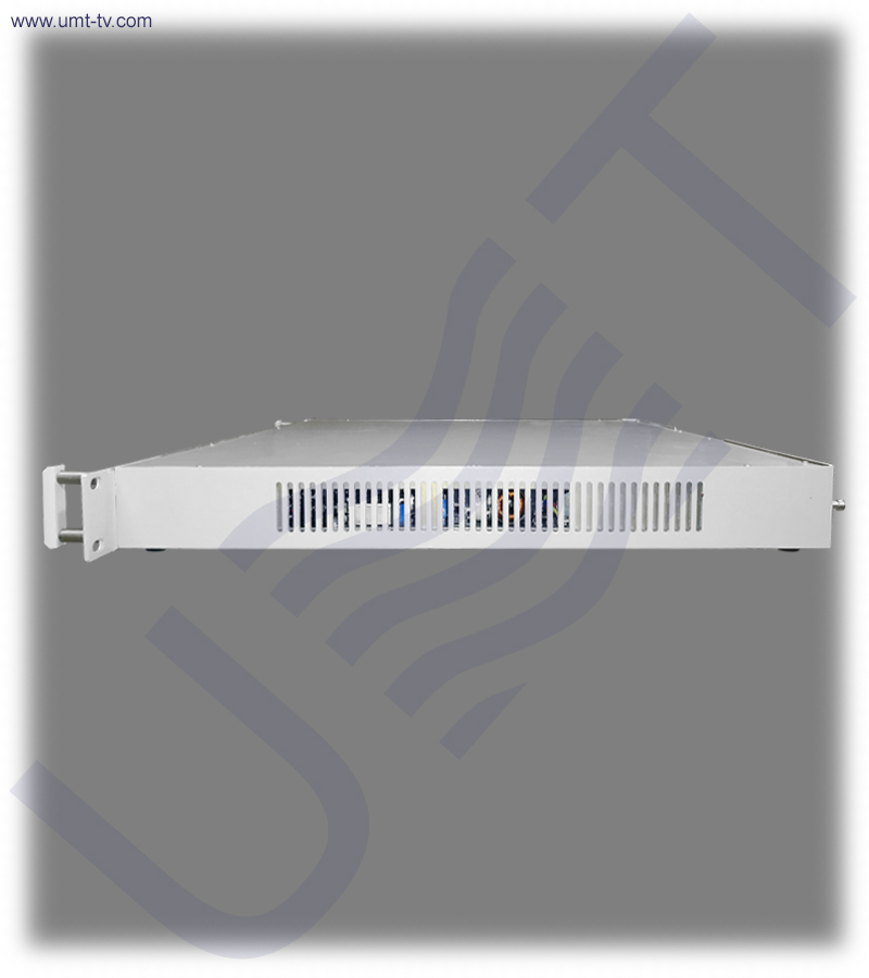
- The structure of the unit, in addition to the frequency converter module, also includes network switching power supplies (AC/DC-converters).
- The parameters of the downconverter can be controlled using buttons which are located on the front panel.
- The set parameters can be seen using LCD on the front panel.
- In the presence of unlock in the PLL circuits of the converter module, the red LED “ALARM” on the front panel will be ON.
- The downconverter can be mounted in standard 19″ rack. The height of downconverter is 1U.
MAIN FUNCTIONS:
- Frequencies converting into L-band when operating in the satellite communication and television L, S, C, X and Ku-bands systems to the standard 70 MHz IF signal for further processing on this IF.
- Monitoring and signaling the presence of unlock in the PLL circuits of the converter module.
- The gain factor adjusting using variable step attenuator with control depth of 30 dB.
| Input parameters: | |
| Input frequency range, MHz | from 950 to 2150 |
| Frequency tuning step, kHz | 1 |
| Frequency instability, ppm | 0.01 |
| Phase noise power spectral density, dBc/Hz: | |
| 100 Hz | – 70 |
| 1 kHz | – 90 |
| 10 kHz | – 95 |
| 100 kHz | – 95 |
| 1 MHz | – 100 |
| Channel Bandwidth, MHz | 36 |
| The maximum allowable input signal level, dBm | – 20 |
| Input impedance, Ohm | 50 |
| Input return loss, dB | – 18 |
| Output parameters: | |
| Output power level with 1dB compression (P1dB out), dBm, not less than | 0 |
| The IMD3 value with two output signals of -13dBm, dBm, not more than | – 40 |
| Conversion gain, dB, not less than | 30 |
| Gain adjustment depth, dB, not less than | – 30 |
| Gain adjustment step, dB | 1.0 |
| Impedance of radio frequency output, Ohm | 50 |
| VSWR of radio frequency output | 1.8:1 |
| Spurious emissions in the working band, dB, not more than | – 60 |
| Control and monitoring: | |
| Control and monitoring mode | Local and remote |
| Remote mode interface | Ethernet 10/100 Base T |
| Reference oscillator: | |
| Reference oscillator frequency, MHz | 10 |
| Phase noise of the reference oscillator, dBc/Hz: | |
| 10 Hz | -125 |
| 100 Hz | -140 |
| 1 kHz | -150 |
| 10 kHz | -155 |
| Power supply: | |
| AC power supply voltage with frequency 50Hz, V | 100 – 262 |
| Mechanical: | |
| Overall dimensions (without connectors), mm | 482 х 300 х 44 |
| Weight, kg, not more than | 5.0 |
L-band to 70 MHz Downconverter is a professional dual-conversion IF converter engineered for satellite communication systems, broadcast headends, RF laboratories and high-precision monitoring applications. Designed to convert 950–2150 MHz L-band signals into a clean and stable 70 MHz IF output, it provides exceptional phase-noise performance, low spurious emission (−60 dBc) and precise frequency stability through a high-accuracy 10 MHz reference oscillator.
L-band to 70 MHz Downconverter integrates a fully managed RF chain that includes a 30 dB step attenuator (1 dB steps), high-linearity mixer stages, multi-stage filtering and 0.01 ppm frequency stability. Its dual-conversion architecture (L → 2400 MHz → 70 MHz) ensures high performance even in demanding RF environments with strong interference or dynamic input levels. With local control via front-panel buttons and LCD display, plus Ethernet 10/100 Base-T remote monitoring, it is ideal for both standalone operation and integration into complex RF infrastructures.
✅ High-stability dual-conversion architecture
This L-band to 70 MHz Downconverter uses a dual-conversion chain (L-band → 2400 MHz → 70 MHz) to guarantee excellent IF purity and minimal intermodulation. This architecture ensures low spurious levels (−60 dBc) and high linearity even with wideband input signals. The multi-stage filtering dramatically improves selectivity and protects downstream equipment from overload or interference.
✅ Precision frequency control with 1 kHz tuning step
The converter supports a fine tuning step of 1 kHz, allowing accurate frequency alignment for satellite monitoring, test benches and IF processing systems. With an extremely stable local oscillator (0.01 ppm), the downconverter maintains consistent IF frequency output under varying temperature and load conditions, ensuring long-term accuracy.
✅ Advanced monitoring with LCD and PLL alarm
Equipped with a front-panel LCD display, the device provides real-time readout of operating frequency, attenuation settings and system status. The integrated PLL alarm LED instantly notifies the operator of reference loss or oscillator unlock, protecting the integrity of mission-critical broadcast and communication paths.
🛠️ Whether you need a professional L-band to 70 MHz IF converter, a dual-conversion downconverter for satellite systems, or a 70 MHz IF downconverter with Ethernet monitoring and PLL alarm indication, the L-band to 70 MHz Downconverter is a stable and integration-ready solution for demanding RF infrastructures.
🛒 Designed for 24/7 operation, the L-band to 70 MHz Downconverter includes AC/DC power modules, PLL alarm indication and a robust mechanical construction suitable for standard 19-inch rack systems (1U height). Its low phase noise, stable conversion gain and precise tuning step make it a reliable choice for professional satellite IF downlink chains, telemetry systems, monitoring stations and redundant converter configurations.
📌 Key features
-
Dual-conversion L-band to 70 MHz downconverter
The signal path converts L-band (950–2150 MHz) to 70 MHz IF through an intermediate 2400 MHz stage. This dual-conversion method significantly enhances image rejection and spurious suppression. It ensures clean output even in high-density RF installations such as satellite hubs and professional ground stations.
-
30 dB variable step attenuator (1 dB steps)
A built-in 30 dB RF attenuator allows precise gain control for input level equalization or dynamic signal management. This feature helps maintain optimal IF output levels and prevents overload conditions. It is especially valuable in systems with variable LNB or tuner outputs.
-
0.01 ppm high-accuracy reference oscillator
The internal 10 MHz reference oscillator provides exceptional frequency stability with extremely low phase noise (−155 dBc/Hz at 10 kHz). This ensures excellent MER/BER performance in downstream demodulators and prevents long-term drift in continuous operation systems.
-
Front-panel LCD and local control keys
All operational parameters, including tuning frequency, attenuation and operating status, are accessible via the front-panel LCD interface. This allows technicians to configure and test the downconverter quickly without external devices.
-
Ethernet remote control and monitoring
The device supports full-status remote control via Ethernet (10/100 Base-T). This gives operators the ability to manage frequency, gain and alarms from a central NOC, simplifying integration into automated monitoring and redundancy systems.
⚙️ Main functions
-
L-band to 70 MHz frequency conversion for satellite systems
The downconverter is designed for use in satellite broadcast, telemetry, MVDS and professional RF systems. It converts wideband L-band signals to a standard 70 MHz IF suitable for demodulators, analyzers and up/downconverter chains.
-
PLL lock detection and alarm signaling
The system continuously monitors PLL lock status and triggers the red “ALARM” LED if instability or reference failure occurs. This provides rapid fault detection to prevent degradation of downstream equipment.
-
Gain adjustment through 30 dB attenuator
With fine resolution control (1 dB steps), operators can maintain stable output levels across varying input power conditions. This ensures optimal performance for receivers and IF processors.
-
Local and remote operation modes
Technicians can switch between front-panel control and remote Ethernet operation, making the device versatile for both laboratory testing and field deployment.
🧩 Applications
-
Satellite ground stations and teleports
This downconverter is an essential component for satellite ground stations requiring precise L-band to 70 MHz IF translation for stable demodulation and monitoring workflows. Its low phase noise, fine 1 kHz tuning steps and 0.01 ppm oscillator stability ensure accurate carrier tracking and minimal BER degradation. The unit supports DVB-S/S2, telemetry downlinks, carrier monitoring systems and advanced satellite measurement setups.
-
Broadcast and MVDS headends
The converter integrates seamlessly into professional digital TV distribution chains where stable 70 MHz IF is required for modulation, re-modulation and regeneration stages. Its excellent spurious suppression (−60 dBc) and high conversion gain ensure a clean IF feed even in multi-carrier headend environments. Designed for 24/7 operation, it enhances the reliability of MVDS, DVB-T/T2 and regional TV broadcast hubs.
-
Redundant downconverter systems (1+1 / N+1)
The device supports both 1+1 and N+1 redundant architectures thanks to its PLL alarm logic, Ethernet monitoring and stable IF output matching professional redundancy matrices. In mission-critical RF facilities, automatic failover systems rely on the unit’s fast detection of PLL unlock or IF chain instability. Its high frequency accuracy ensures that redundant modules operate in perfect synchronization, preventing phase jumps or demodulation errors.
-
RF laboratories, R&D centers and test environments
The downconverter is widely used in RF labs and development centers requiring precise and repeatable 70 MHz IF outputs for equipment characterization and signal simulation. Its extremely low phase noise and fine tuning step allow engineers to replicate real satellite conditions for receiver testing, filtering experiments and signal-integrity analysis. The adjustable 30 dB attenuator provides flexible level control needed for controlled lab measurements.
💡 Why you should buy from us❓
- 1.5 years warranty
- 7 years after-sales support
- Remote support team of engineers
- Discount program for regular customers 🎁
💬 Contact Us
For additional details or assistance regarding the L-band to 70 MHz Downconverter, feel free to contact our team. We provide professional consultation and aftersales support to help with installation and setup, ensuring you get the most out of your broadcasting equipment.
Documentation