2229
Upconverter 1+1
Short description
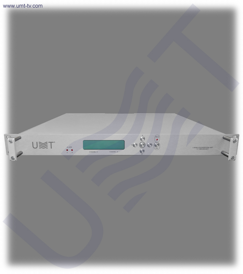
Upconverter with 1+1 redundancy is designed to convert signals from 70 MHz IF to L-band for processing in satellite communication systems of L, S, C, X and Ku bands.
Request for customized equipment HEAD-END
-
Description
-
Downloads
Upconverter with 1+1 redundancy is applied in large earth stations where cost-effective frequency converter solutions are required. Lightweight, durable and compact design ensures that the upconverter with 1+1 redundancy is effective solution for mobile reporting stations. Thanks to aluminum chassis and solid modular interior design, the upconverter with 1+1 redundancy can be installed on military targets. Upconverter with 1+1 redundancy have a large MTBF value, which is more than 120,000 hours.
Upconverter with 1+1 redundancy can be used in VSAT stations, SCPC networks, reporting stations of SNG type, DVB-RCS systems and hubs, and any other systems where compact backup systems are needed.
KEY FEATURES:
- Upconverter with 1+1 redundancy includes the separate frequency converter block, detector module, power supply and reference oscillator.
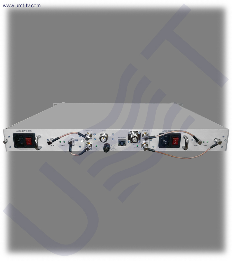
- Upconverter with 1+1 redundancy consists of two frequency converters, which are integrated in the case of 1RU and can be automatically replaced in "hot" mode (1+1 scheme).
- It is possible to replace a separate converter block with spare redundant unit without shutting down the chassis.
- Upconverter with 1+1 redundancy provides automatic (in case of failure of one of the blocks) or manual switching between the blocks of frequency converters.
- Each converter is a completely autonomous device, which is executed as a replacement block.
- Replacement blocks are frequency converters with dual conversion of 70 MHz / 2400 MHz / L.
- It has local control from the front panel, which has LCD, LEDs and buttons.
- Upconverter with 1+1 redundancy provides complete remote control via Ethernet interface connector located on the rear panel.
MAIN FUNCTIONS:
- Provides the signals frequency conversion from the range of 50 - 90 MHz to the L-band (950-2150 MHz) when working in stations of satellite communication and television (L, S, C, X and Ku frequency bands).
- Provides automatic "hot" backup of converter blocks, reference generators and power supply units according to the scheme 1+1.
- Provides automatic switching to the backup unit when one of the blocks is broken.
- Provides the gain factor adjusting either using buttons on the front panel or remotely.
| Parameter name, units | Nominal value, tolerance |
|---|---|
| Input operating frequency range, MHz | from 52 to 88 |
| Uneven frequency response in the input operating frequencies range, dB, not more than | 1.0 |
| Frequency adjusting step, kHz | 1 |
| Frequency instability, ppm | 0.01 |
| Spectral density of phase noise power, dBc/Hz, in case of detuning from carrier on:
100 Hz |
-70 |
| Frequency bandwidth at output, MHz | 36 |
| Unequal frequency response in the bandwidth 36MHz at the output range 950 – 2150 MHz, dB, not more than | 5.0 |
| Maximum acceptable level of the input signal (at attenuation 20 dB), dBm | – 20 |
| The output power level at 1dB compression (P1dB), dBm, not less than | 0 |
| The value of the IMD3 in the presence of two output signals with a power of -13dBm, dBm, not more than | – 40 |
| Maximum conversion gain, dB, not less than | 50 |
| Depth of the gain factor adjustment due to two attenuators, dB, not less than | – 50 |
| Step of adjusting the gain factor, dB | 1.0 |
| Impedance of radio frequency input, Ohm | 50 |
| Return losses at the input, dB | – 18 |
| Management and control mode | Local and remote |
| Remote mode interface | Ethernet 10/100 Base T |
| Impedance of output, Ohm | 50 |
| Output VSWR | 1.8:1 |
| Spurious radiation in the working frequency range, dBc, not more than | – 55 |
| Frequency of reference oscillator, MHz | 10 |
| Phase noise of the reference oscillator, dBc/Hz when detuning from carrier on: 10 Hz |
-125 |
| AC power supply voltage with frequency of 50 Hz, V | 100 – 262 |
| Power consumed in “hot” redundency mode (1+1), W, no more than | 45 |
| Overall dimensions (without connectors), mm | 482 х 400 х 44 |
| Weight, kg, no more than | 7.0 |
Documentation


