Upconverter with 1+1 redundancy is applied in large earth stations where cost-effective frequency converter solutions are required.
Lightweight, durable and compact design ensures that the upconverter with 1+1 redundancy is effective solution for mobile reporting stations.
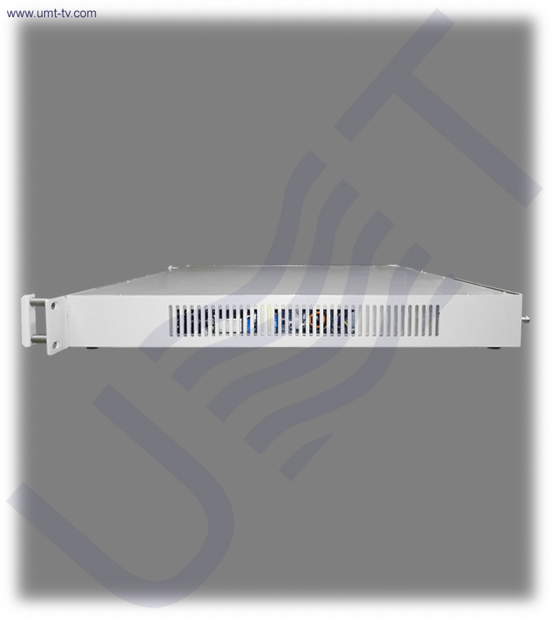
Thanks to aluminum chassis and solid modular interior design, the upconverter with 1+1 redundancy can be installed on military targets. Upconverter with 1+1 redundancy have a large MTBF value, which is more than 120,000 hours.
Upconverter with 1+1 redundancy can be used in VSAT stations, SCPC networks, reporting stations of SNG type, DVB-RCS systems and hubs, and any other systems where compact backup systems are needed.
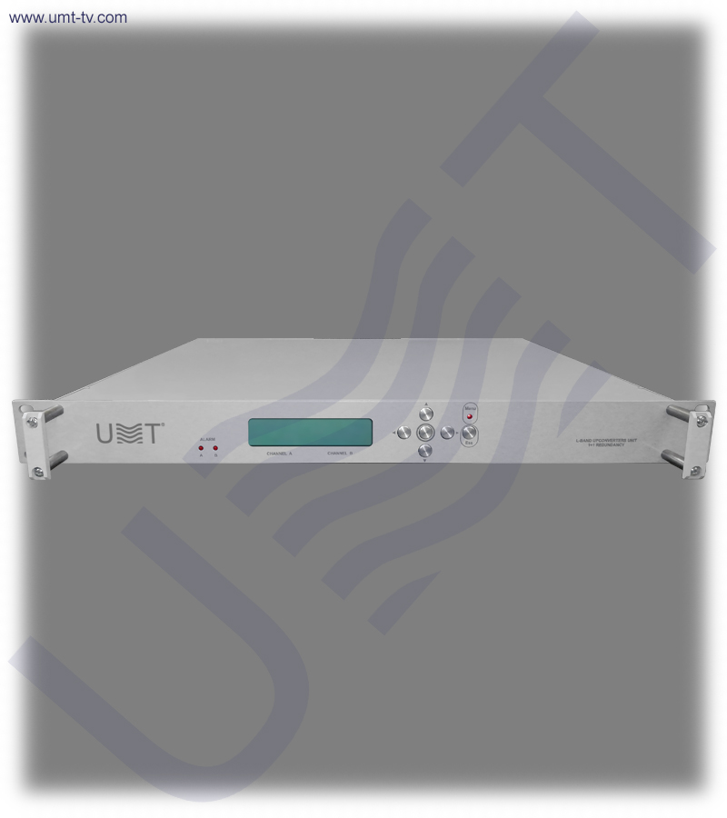
Upconverter 1+1 is a high-reliability 70–90 MHz to L-band RF upconverter designed for satellite uplink systems, DVB-RCS hubs, SCPC networks, SNG vehicles and military communication platforms. Built around a dual hot-redundant architecture, it delivers continuous, uninterrupted operation even in the event of hardware failure. Its rugged aluminum chassis, modular interior blocks and long MTBF (>120,000 hours) make it suitable for stationary teleports, mobile broadcast trucks and field-deployed communication systems.
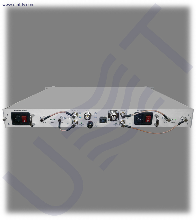
Engineered with dual-conversion technology (70 MHz → 2400 MHz → L-band), the Upconverter 1+1 provides low phase noise, high spectral purity and stable conversion characteristics across the full 950–2150 MHz output range. Local front-panel control with LCD and LEDs ensures instant status visibility, while full Ethernet 10/100 remote management enables seamless integration into modern NMS and automated uplink infrastructures.
✅ High-reliability 1+1 redundant upconversion system
The upconverter integrates two fully autonomous converter blocks operating in hot standby, ensuring uninterrupted RF output during equipment faults. Its redundancy supervisor monitors RF level, IF level, PLL lock and power supply status to trigger instant failover when required. Hot-swap capability allows technicians to replace individual converter modules without shutting down the chassis, providing exceptional uptime in mission-critical satellite networks.
✅ Advanced dual-conversion 70 MHz → 2400 MHz → L-band architecture
The dual-conversion system significantly improves spectral purity while minimizing IMD3, spurious components and phase noise. A high-stability 10 MHz reference oscillator (0.01 ppm) ensures accurate and predictable output frequencies across 950–2150 MHz. The converter maintains excellent linearity and stable gain characteristics, ensuring compatibility with DVB-S/S2, DVB-RCS, SCPC and other satellite modulation schemes.
✅ Comprehensive local and remote management with Ethernet control
Front-panel LCD, LEDs and keypad offer full local configuration of gain, attenuation, switching logic and monitoring functions. Ethernet remote control enables operators to manage the converter from teleports, NOCs or automated uplink controllers. Detailed alarm reporting improves fault diagnosis and ensures quick maintenance intervention. The system provides granular gain adjustment up to 50 dB in 1 dB steps, enabling fine IF-to-RF power optimization for any uplink topology.
🛠️ The Upconverter 1+1 provides operators with a fault-tolerant RF conversion chain capable of meeting stringent broadcast, VSAT and tactical communication requirements. Its automatic switchover system detects failures in RF levels, PLL lock, reference stability or power supply performance, ensuring that the backup module takes over instantly. Hot-swappable converter blocks and PSU modules further minimize downtime, enabling rapid on-site maintenance without interrupting L-band transmission.
🛒 With its compact 1RU rackmount chassis, extremely low phase-noise oscillator and wide gain adjustment range (50 dB), the Upconverter 1+1 offers both performance and flexibility. It is ideal for integration into multi-carrier uplinks, mobile SNG systems, military communication shelters and DVB-RCS gateways that require continuous, stable L-band output under all operational conditions.
📌 Key features
-
1+1 hot-redundant conversion system with automatic switching
The upconverter integrates two independent converter blocks operating with automatic hot-standby switching. In the event of failure, the backup module instantly assumes the active role, guaranteeing continuous L-band output. Hot-swap capability ensures minimal downtime and uninterrupted uplink operation.
-
Dual-conversion chain (70 MHz → 2400 MHz → L-band)
The frequency plan enhances filtering and spectral cleanliness while reducing image and spurious responses. This architecture results in stable and predictable RF output suitable for high-performance satellite modulation systems. Low phase-noise performance ensures optimal demodulator operation at the receiving end.
-
50 dB gain adjustment with dual attenuators
The upconverter includes two attenuators providing a combined control depth of 50 dB in precise 1 dB steps. This facilitates accurate RF power matching for multi-carrier uplinks, SNG stations and tactical communication terminals. Operators can adjust levels from the front panel or remotely via Ethernet.
-
Military-grade aluminum chassis with long MTBF
The rugged chassis and modular construction provide durability for mobile and harsh environments. An MTBF exceeding 120,000 hours ensures exceptionally stable long-term operation in both indoor and field-deployed infrastructures. Lightweight construction also supports airborne and vehicle-mounted installations.
-
Complete local and remote control interface
The device provides full configuration capabilities via the front LCD and buttons, allowing for rapid onsite adjustments. Remote control over Ethernet 10/100 enables integration with automated systems and centralized management platforms. LEDs provide real-time visual feedback on status, alarms and module activity.
⚙️ Main functions
-
Upconversion from 50–90 MHz to L-band (950–2150 MHz)
Converts standard 70 MHz IF and adjacent frequency ranges into clean L-band carriers. Supports DVB-RCS, SCPC, VSAT and SNG uplink architectures requiring high stability and low noise. The wide output range ensures compatibility with upconverters, BUC drivers and RF distribution systems.
-
Automatic redundant switching according to 1+1 scheme
Continuously monitors both converter chains and switches to the redundant module when faults occur. Ensures uninterrupted uplink operation during equipment failure, maintenance or converter replacement. ALARM logic evaluates RF levels, IF levels and PLL lock stability for reliable decision-making.
-
Local and remote gain control with high precision
Internal attenuators allow fine optimization of output levels for diverse uplink equipment. Remote control helps operators quickly adjust gain to match varying modulation schemes or multi-carrier requirements. Local front-panel control supports on-site technicians and rapid deployment.
-
Integrated fault monitoring and alarm logic
The detector module analyzes signal presence, PLL lock, reference oscillator status and power supply health. All alarm conditions are logged and available locally or via remote monitoring. This enables proactive maintenance, reducing downtime and operational disruptions.
🧩 Applications
-
VSAT hubs, DVB-RCS gateways and satellite teleports
Provides clean and stable L-band carriers required for uplink chains in large satellite hubs. Ensures continuous service through 1+1 automatic redundancy and hot-swap capability. Its excellent spectral purity and gain stability make it suitable for multi-carrier loading.
-
SNG (Satellite News Gathering) and mobile reporting stations
Lightweight construction and compact 1RU design allow easy installation in mobile broadcasting vehicles. High MTBF and ruggedized interior components ensure reliability in vibration-prone or outdoor environments. Automatic redundancy protects critical live transmissions.
-
SCPC networks and tactical military communication systems
Supports narrowband and wideband uplinks with precise frequency stability and low phase noise. Aluminum chassis and modular layout allow installation at remote or military targets. The device integrates well with encrypted uplink terminals and field communication shelters.
-
RF laboratories and test environments
Offers fine-step frequency control, excellent noise characteristics and wide gain adjustment ideal for research setups. Engineers can test RF chain performance, upconversion stages and modem functionality using accurate L-band outputs. Its stable dual-conversion architecture suits demanding measurement tasks.
💡 Why you should buy from us❓
- 1.5 years warranty
- 7 years after-sales support
- Remote support team of engineers
- Discount program for regular customers 🎁
💬 Contact Us
For additional details or assistance regarding the Upconverter 1+1, feel free to contact our team. We provide professional consultation and aftersales support to help with installation and setup, ensuring you get the most out of your broadcasting equipment.